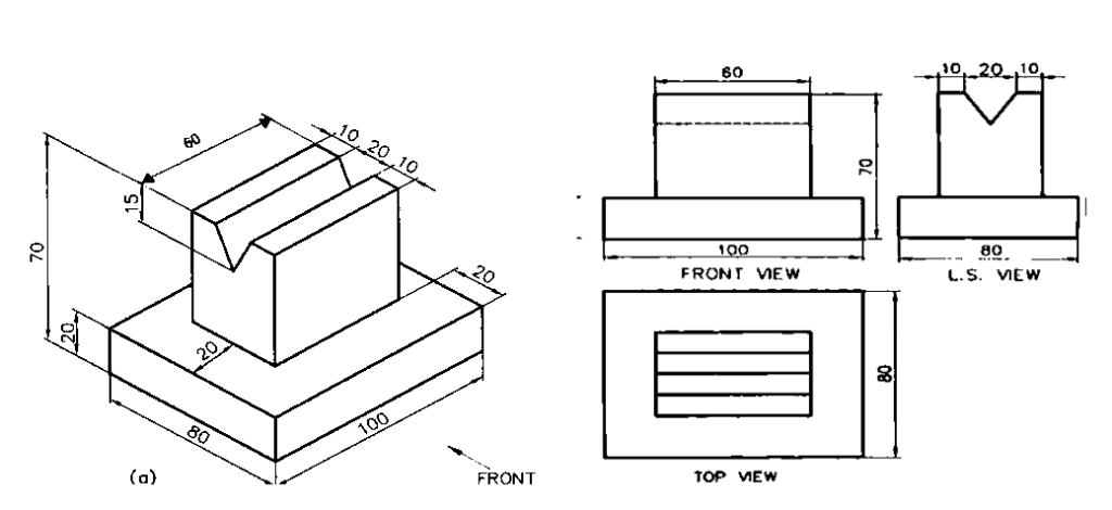
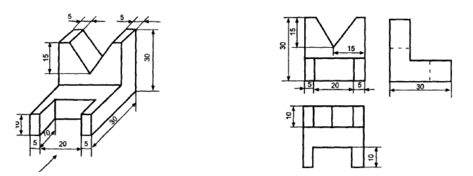
The core theme of the article “Engineering Graphics – Conversion of Views – Isometric to Orthographic Views & Orthographic to Isometric Views” deals with conversion of isometric projections into orthographic views and vice versa. In The field of engineering graphics. It is a core requisite skill to learn how to properly represent 3D objects into 2D drawings, and with the knowledge of these conversions this would be possible.
Isometric Projections: The article defines isometric projections and their important in engineering drawings. It states the importance of isometric axes which are lines that intersect at an angle of 120 and makes a difference between isometric and non isometric lines.
Orthographic Projections: The content deals with orthographic projections them introducing features of the object drawn which may include its front, the top and the side view among other features when drawing orthographic views of the object.
Conversion Techniques: This article explains every step that is necessary in changing isometric views to orthographic projections and back again. Methods of converting or changing a three-dimensional view of an object to a two-dimensional view and understanding orthographic projections to form isometric views are included.
Practical Exercises: To Extends and challenge the knowledge acquired, the article further outlines practical problems that may include the drawing of isometric projections of hexagonal prisms , cylinders and other objects. These exercises aim at sharpening the reader’s skills on the application of the conversion techniques that have been discussed.
The important terms used in convention projections are as follows:
- Isometric axes The three lines CB, CD and CG, meeting at point C and inclined at an angle of 120°
with each other, are called isometric axes. - Isometric lines The lines parallel to the isometric axes are called isometric lines. Here lines AB, BF,
FG, GH, DH and AD are isometric lines. - Non-isometric lines The lines which are not parallel to isometric axes are known as non-isometric
lines. Here diagonals BD, AC, CF, BG, etc., are non-isometric lines. - Isometric plane The plane representing any face of the cube as well as other plane parallel to it is
called an isometric plane. Here, ABCD, BCGF, CGHD, etc., are isometric planes. - Non-isometric plane The plane which is not parallel to isometric planes are known as non-isometric
planes. Here, the plane ABGH, CDEF, AFH, CFH, etc., are non-isometric planes. - Isometric scale It is the scale which is used to convert the true length into isometric length. Mathematically,
Isometric length = 0.816 * True length
Problem: Draw the isometric view of a hexagonal prism of base side 30 and axis 70 mm. The prism is resting on its base on the H.P. with an edge of the base parallel to the V.P.

Problem: Draw an isometric projection of a pentagonal prism of base side 35 mm and axis 60 mm. The prism rests on its base on the H.P. with an edge of the base parallel to the V.P.

Problem: Draw the isometric view of a cylinder of base diameter 50 mm and axis 60 mm. The axis of the cylinder is perpendicular to the V.P.

Problem: Draw (i) Front View (ii) Top View (iii) Side View of the given object.

Problem: Draw (i) Front View (ii) Top View (iii) Side View of the given object.

Problem: Draw (i) Front View (ii) Top View (iii) Side View of the given object.

Problem: Draw (i) Front View (ii) Top View (iii) Side View of the given object.

Problem: Draw (i) Front View (ii) Top View (iii) Side View of the given object.

Final Words
It makes sure that the message in design is well communicated. Someone who is able to understand and implement techniques highlighted in the article should know how to switch between these two projection methods, resulting in better technical documentation.


